One stop supplier of water treatment parts&accessories

Decoding Diagram Reverse Osmosis: A Comprehensive Guide
Introduction
Reverse osmosis (RO) is a pivotal water treatment process. But what does a diagram reverse osmosis actually show? Let’s find out. RO diagrams are crucial tools for understanding how this technology purifies water. They’re used in industries like food, healthcare, and even in our daily lives, such as in home water filters.
Basics of Reverse Osmosis
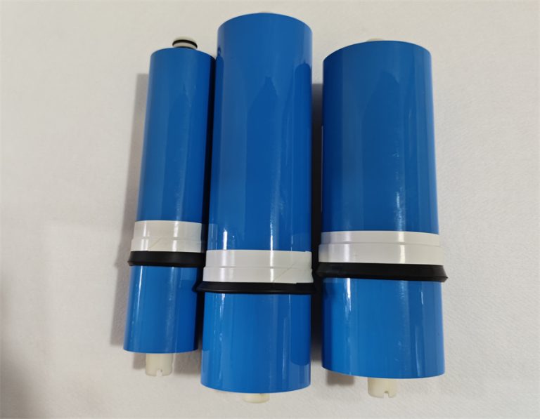
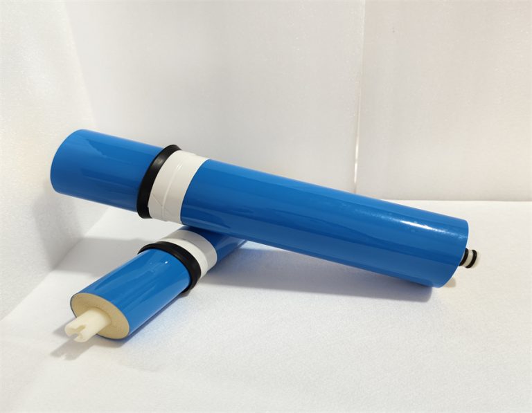
Reverse osmosis is the process of forcing water through a semi – permeable membrane. This membrane allows water molecules to pass but blocks contaminants. A diagram reverse osmosis typically shows water flow, the membrane, and the separation of pure water from impurities. For example, in a simple RO setup, pressure is applied to the impure water side, pushing clean water through the membrane.
Key Components in a Diagram Reverse Osmosis
| Component | Function |
| Semi – permeable Membrane | Filters out contaminants |
| Pressure Vessel | Holds the membrane and withstands pressure |
| Feed Water Inlet | Brings in impure water |
| Permeate Outlet | Releases purified water |
| Concentrate Outlet | Removes concentrated contaminants |
The Problem: Water Contamination
Water contamination is a global concern. According to the United Nations, about 785 million people lack access to clean water (UN Water, 2017). Contaminants can be physical, chemical, or biological. In developing countries, water – borne diseases are a leading cause of death. For instance, in some rural areas, water sources are contaminated with bacteria and heavy metals, making the water unsafe to drink.
How Diagram Reverse Osmosis Solves the Problem
A diagram reverse osmosis clearly shows how water purification occurs. By applying pressure, water is pushed through the membrane. The membrane acts as a fine filter, removing particles as small as 0.0001 microns. This includes bacteria, viruses, and dissolved salts. As a result, clean water is obtained on the other side.
Case Study: Our Team’s Experience
Our team worked on a project in 2024. We were helping a small community in a drought – prone area. They had a water source with high salt content. By studying a diagram reverse osmosis, we designed a system. After installation, the water quality improved significantly. The RO system removed the excess salts, making the water suitable for drinking and daily use.
Types of Reverse Osmosis Systems
There are different types of RO systems, each with its own diagram. Let’s look at two common ones:
Home – based RO Systems
Home RO systems are designed for small – scale water purification. Their diagrams usually show a simple setup with a pre – filter, RO membrane, and storage tank. They are easy to install and maintain. However, they have a lower water output compared to commercial systems. For example, a typical home RO system can produce around 50 – 100 gallons of purified water per day.
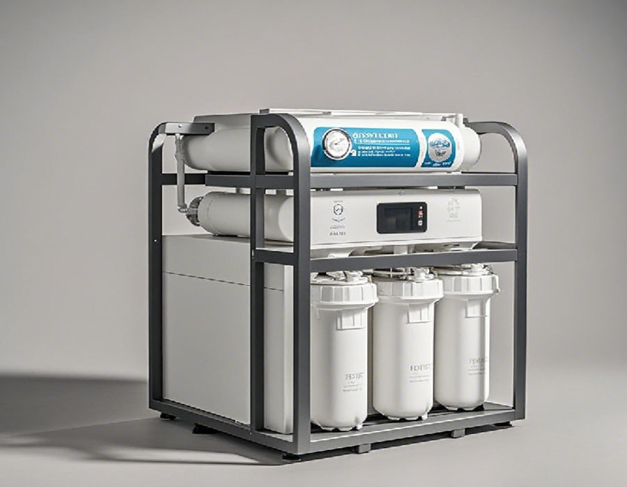
Commercial RO Systems
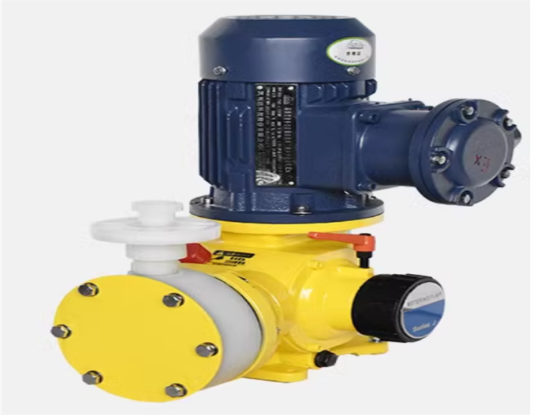
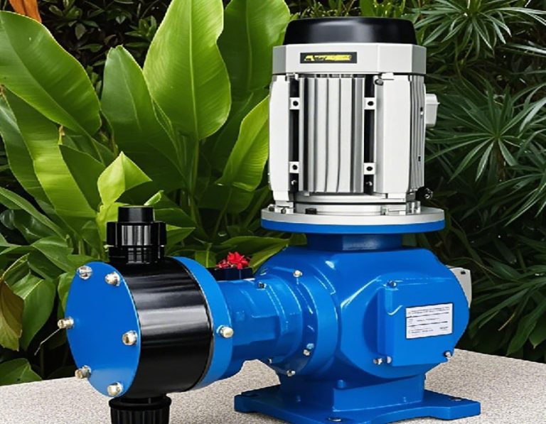
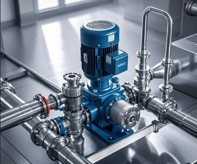
Commercial RO systems are more complex. Their diagrams show multiple membrane modules, high – pressure pumps, and advanced control systems. These systems are used in large – scale applications like factories and water treatment plants. They can process thousands of gallons of water per hour. But they require more maintenance and a higher initial investment.
Comparison Table: Home – based vs Commercial RO Systems
| Feature | Home – based RO | Commercial RO |
| Water Output | 50 – 100 gallons per day | Thousands of gallons per hour |
| Complexity | Low | High |
| Initial Investment | Low | High |
| Maintenance | Easy | Requires more expertise |
Installation and Operation of Reverse Osmosis Systems
Installing an RO system requires careful steps. Here’s a guide based on a diagram reverse osmosis:
- Site Preparation: First, select a suitable location. Ensure there’s access to water and electricity. The area should be clean and well – ventilated.
- Component Assembly: Assemble the RO system components as per the diagram. This includes installing the membrane, connecting pipes, and setting up pumps.
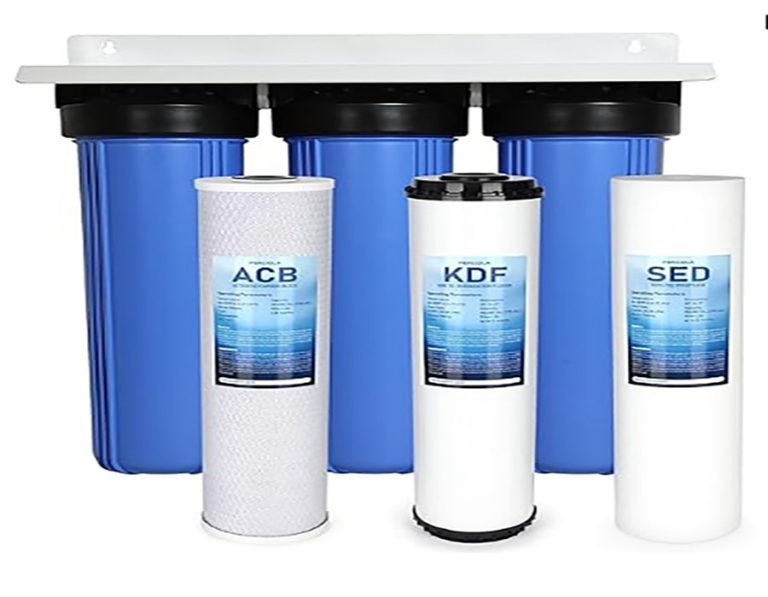
- Pre – treatment Setup: Install pre – filters to remove large particles. This protects the RO membrane from damage.
- System Testing: Before full – scale operation, test the system. Check for leaks and ensure proper water flow.
- Operation and Monitoring: Regularly monitor the system. Check water quality, pressure levels, and membrane performance.
⚠ Warning: A common mistake is not replacing pre – filters regularly. This can cause the RO membrane to clog, reducing its efficiency.
Case Study: A Bottling Plant’s RO Success
A bottling plant we worked with was facing issues with water quality. Their old water treatment system was not removing enough contaminants. By implementing a new RO system, as guided by its diagram, they were able to improve water quality. The RO system removed all impurities, ensuring the bottled water met high standards. Their production increased, and they faced fewer product recalls.
Future Trends in Reverse Osmosis Technology
The future of reverse osmosis looks exciting. New materials are being developed for membranes. For example, there are efforts to create membranes with higher water permeability. Another trend is the development of more energy – efficient RO systems. This is important as RO systems can consume a significant amount of energy.
Conclusion
Diagram reverse osmosis is a powerful tool for understanding and implementing water purification. It offers solutions to water contamination problems. By following the installation and operation steps, and avoiding common mistakes, we can ensure effective use of RO systems. Here’s a checklist for using reverse osmosis systems:
- Check water quality before installation.
- Follow the installation steps carefully.
- Replace pre – filters regularly.
- Monitor water quality and system performance.
- Stay updated on new RO technologies.
In summary, reverse osmosis is a key technology for a cleaner and healthier future.